
Projection Methods
Universally either the 1st angle projection or the third angle
projection methods is followed for obtaining engineering drawings. The
principal projection planes and quadrants used to create drawings are shown in
figure 16. The object can be considered to be in any of the four quadrant.

First Angle Projection
In this the object in assumed to be positioned in the first
quadrant and is shown in figure 17 The object is assumed to be positioned in
between the projection planes and the observer. The views are obtained by
projecting the images on the respective planes. Note that the right hand side
view is projected on the plane placed at the left of the object. After
projecting on to the respective planes, the bottom plane and left plane
is unfolded on to the front view plane. i.e. the left plane is unfolded
towards the left side to obtain the Right hand side view on the left side of
the Front view and aligned with the Front view. The bottom plane is unfolded
towards the bottom to obtain the Top view below the Front view and aligned with
the Front View.

Third Angle Projection
In
the third angle projection method, the object is assumed to be in the third
quadrant. i.e. the object behind vertical plane and below the horizontal plane.
In this projection technique, Placing the object in the third quadrant puts the
projection planes between the viewer and the object and is shown in figure
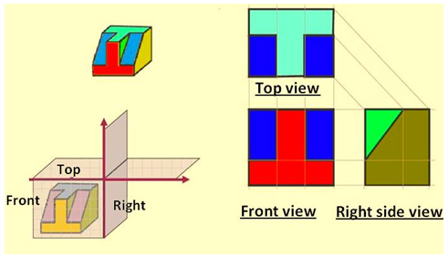
Figure illustrates the difference between the 1st angle and 3rd angle projection
techniques. A summary of the difference between 1st and 3rd angle projections
is shown

Difference between first-
and third-angle projections

Either first angle projection or third angle projection
are used for engineering drawing. Second angle projection and fourth
angle projections are not used since the drawing becomes complicated. This is
being explained with illustrations in the lecture on Projections of points
(lecture 18).
Symbol of projection
The type of projection obtained should be indicated symbolically
in the space provided for the purpose in the title box of the drawing sheet.
The symbol recommended by BIS is to draw the two sides of a frustum of a cone
placed with its axis horizontal The left view is drawn.

I have found that this site is very informative, interesting and very well written. keep up the nice high quality writing Sell Your Obsolete Automation Parts NZ
ReplyDelete