
Lines
Lines is one important aspect of technical drawing. Lines are always used to construct meaningful drawings. Various types of lines are used to construct drawing, each line used in some specific sense. Lines are drawn following standard conventions mentioned in BIS (SP46:2003). A line may be curved, straight, continuous, segmented. It may be drawn as thin or thick. A few basic types of lines widely used in drawings are shown in Table 1.
Lines is one important aspect of technical drawing. Lines are always used to construct meaningful drawings. Various types of lines are used to construct drawing, each line used in some specific sense. Lines are drawn following standard conventions mentioned in BIS (SP46:2003). A line may be curved, straight, continuous, segmented. It may be drawn as thin or thick. A few basic types of lines widely used in drawings are shown in Table 1.
Table 1. Types of letters used in engineering drawing.

Line Strokes
Line strokes refer to the directions of drawing straight and curved lines. The standards for lines is given in BIS : SP-46, 2003
Vertical and inclined lines are drawn from top to bottom, horizontal lines are drawn from left to right. Curved lines are drawn from left to right or top to bottom. The direction of strokes are illustrated in figure 1.

Conventions used in lines
· 1. International systems of units (SI) – which is based on the meter.
· 2. Millimeter (mm) - The common SI unit of measure on engineering drawing.
· 3. Individual identification of linear units is not required if all
dimensions on a drawing are in the same unit (mm).
· 4. The drawing should contain a note: ALL DIMENSIONS ARE IN MM. (Bottom
left corner outside the title box)
5.Typical figures showing various lines
used in the construction of engineering drawing is shown in figure 2.

A typical use of various lines in an
engineering drawing is shown in figure below:

Dimensioning
The size and other details of the object essential for its construction and function, using lines, numerals, symbols, notes, etc are required to be indicated in a drawing by proper dimensioning. These dimensions indicated should be those that are essential for the production, inspection and functioning of the object and should be mistaken as those that are required to make the drawing of an object. The dimensions are written either above the dimension lines or inserted at the middle by breaking the dimension lines.
The size and other details of the object essential for its construction and function, using lines, numerals, symbols, notes, etc are required to be indicated in a drawing by proper dimensioning. These dimensions indicated should be those that are essential for the production, inspection and functioning of the object and should be mistaken as those that are required to make the drawing of an object. The dimensions are written either above the dimension lines or inserted at the middle by breaking the dimension lines.
Normally two types of dimensioning
system exist. i.e. Aligned system and the unidirectional system.These are shown
in figure 3.
In the aligned system the dimensions
are placed perpendicular to the dimension line in such a way that it may be
read from bottom edge or right hand edge of the drawing sheet. The horizontal
and inclined dimension can be read from the bottom where as all the vertical
dimensions can be read from the right hand side of the drawing sheet.
In the unidirectional system, the dimensions are so oriented such that they can be read from the bottom of the drawing.
In the unidirectional system, the dimensions are so oriented such that they can be read from the bottom of the drawing.

Rules to be followed for dimensioning.
Refer figure 4.
1. Each feature is dimensioned and positioned only once.
· 2.Each feature is dimensioned and positioned where its shape shows.
· 3Size dimensions – give the size of the component.
· 4. Every solid has three dimensions, each of the geometric shapes making up
the object must have its height, width, and depth indicated in the
dimensioning.

Dimensioning consists of the
following:
·
A thin, solid line that shows the extent and direction of a
dimension. Dimension lines are broken for insertion of the dimension
numbers
·
Should be placed at least 10 mm away from the outline and all
·
other parallel dimensions should be at least 6 mm apart, or more, if
space permits
The important elements of
dimensioning consists of extension lines, leader line, arrows and dimensions.
Extension line – a thin,
solid line perpendicular to a dimension line, indicating which feature is
associated with the dimension. There should be a visible gap of 1.5 mm between
the feature’s corners and the end of the extension line.Figure 5 shows
extension lines.
Leader line
A thin, solid line used to indicate the feature with which a dimension, note, or symbol is associated. Generally this is a straight line drawn at an angle that is neither horizontal nor vertical. Leader line is terminated with an arrow touching the part or detail. On the end opposite the arrow, the leader line will have a short, horizontal shoulder. Text is extended from this shoulder such that the text height is centered with the shoulder line

·
Arrows – 3 mm wide and should be 1/3rd as wide as they are long -
symbols placed at the end of dimension lines to show the limits of the
dimension. Arrows are uniform in size and style, regardless of the size
of the drawing.Various types of arrows used for dimensioning is shown in figure
6.


Dimensioning of angles: The normal convention for dimensioning of angles
are illustrated

Few examples during dimensioning of
solids are shown below:
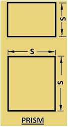
·
Prism – This is the most common shape and requires
three dimensions. Two dimensions shown on the principal view and
the third dimension on the other view.
·
Cylinder – Cylinder is the second most common shape. It requires
two dimensions: diameter and length, both shown preferably on the
rectangular view.

·
Cone – requires two dimensions – diameter of the base and altitude
on the same view and length. Both shown on the rectangular view is preferred.

·
Right pyramids – requires three dimensions – dimensions of the
base and altitude.

·
Spheres – requires only one dimension. i.e. diameter.
However in case of extra features, those dimensions are required to be
provided.

RULES OF DIMENSIONING
1. Between any two
extension lines, there must be one and only one dimension line bearing one
dimension.
2. As far as possible,
all the dimensions should be placed outside the views. Inside dimensions are
preferred only if they are clearer and more easily readable.
3. All the dimensions
on a drawing must be shown using either Aligned System or Unidirectional
System. In no case should, the two systems be mixed on the same drawing.
4. The same unit of
length should be used for all the dimensions on a drawing. The unit should not
be written after each dimension, but a note mentioning the unit should be
placed below the drawing.
5. Dimension lines
should not cross each other. Dimension lines should also not cross any other
lines of the object.
6. All dimensions must
be given.
7. Each dimension
should be given only once. No dimension should be redundant.
8. Do not use an
outline or a centre line as a dimension line. A centre line may be extended to
serve as an extension line.
9. Avoid dimensioning
hidden lines.
10. For dimensions in
series, adopt any one of the following ways.
i.
Chain dimensioning (Continuous dimensioning) All the dimensions are
aligned in such a way that an arrowhead of one dimension touches tip-to-tip the
arrowhead of the adjacent dimension. The overall dimension is placed outside
the other smaller dimensions.
ii.
Parallel dimensioning (Progressive dimensioning) All the dimensions are
shown from a common reference line. Obviously, all these dimensions share a
common extension line. This method is adopted when dimensions have to be
established from a particular datum surface
iii.
Combined dimensioning. When both the methods, i.e., chain
dimensioning and parallel dimensioning are used on the same drawing, the method
of dimensioning is called combined dimensioning.
Great blog. All posts have something to learn. Your work is very good and i appreciate you and hopping for some more informative posts. Selling surplus automation parts NZ
ReplyDeleteCadforyou: Lines And Dimensions >>>>> Download Now
ReplyDelete>>>>> Download Full
Cadforyou: Lines And Dimensions >>>>> Download LINK
>>>>> Download Now
Cadforyou: Lines And Dimensions >>>>> Download Full
>>>>> Download LINK kh